- 您现在的位置:买卖IC网 > Sheet目录1953 > MCP47DA1T-A1E/OT (Microchip Technology)IC DGTL POT 30K 1CH SOT-23-6
MCP47DA1
DS25118C-page 6
2012 Microchip Technology Inc.
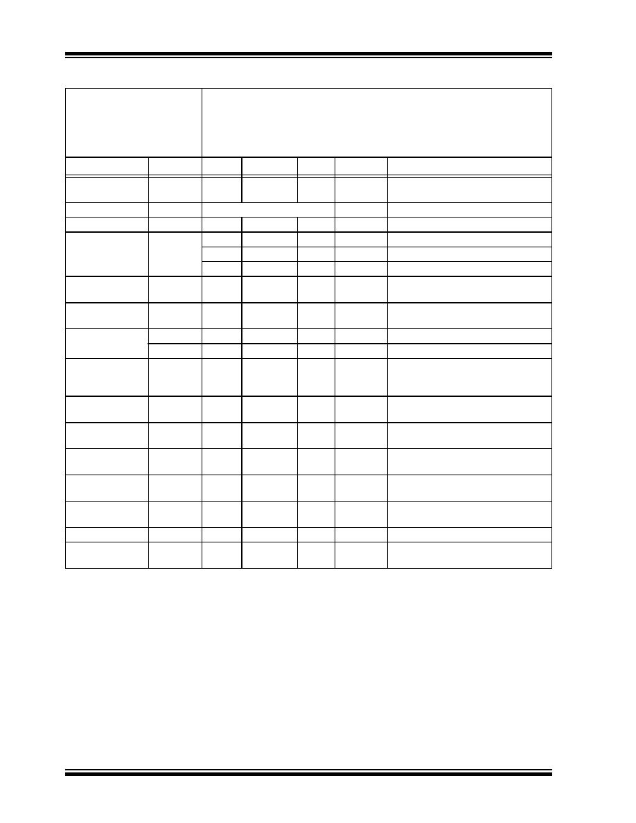
Resistance
(± 20%)
RVREF
24.0
30
36.0
k
Resolution
N
65
Taps
No Missing Codes
Step Resistance
RS
—RVREF / 192
—
Nominal
Resistance
Tempco
R
VREF/T
—
50
—
ppm/°C
TA = -20°C to +70°C
—
100
—
ppm/°C
TA = -40°C to +85°C
—
150
—
ppm/°C
TA = -40°C to +125°C
Ratiometeric
Tempco
V
OUT/T
—
15
—
ppm/°C
Code = Midscale (40h)
VOUT Accuracy
740
750
760
mV
3.0V
V
DD 3.6V
VREF = 1.5V, code = 40h
VOUT Load
LVOUTR
5—
—
k
Resistive Load
LVOUTC
—
1
nF
Capacitive Load
Maximum current
through Terminal
IVREF
——
230
A
VREF = 5.5V
Leakage current
into VREF
IL
—100
—
nA
VREF = VSS
Full-Scale Error
(code = 60h)
VFSE
-1.5
±0.35
+1.5
LSb
2.7V
V
DD 5.5V, VREF = 1.65V
Zero-Scale Error
(code = 20h)
VZSE
-1.5
±0.35
+1.5
LSb
2.7V
V
DD 5.5V, VREF = 1.65V
VOUT Integral
Non-linearity
INL
-0.5
±0.25
+0.5
LSb
2.7V
V
DD 5.5V (Note 2)
VREF = 1.65V
VOUT Differential
Non-linearity
DNL
-0.25
±0.125
+0.25
LSb
2.7V
V
DD 5.5V (Note 2)
VREF = 1.65V
Bandwidth -3 dB
BW
—
100
—
kHz
VREF = 1.5V ± 0.1V, Code = 40h
Capacitance
(VREF)
CREF
—
75
—
pF
f =1 MHz, Code = Full-Scale
AC/DC CHARACTERISTICS (CONTINUED)
DC Characteristics
Standard Operating Conditions (unless otherwise specified)
Operating Temperature
–40°C
T
A +125°C (extended)
All parameters apply across the specified operating ranges unless noted.
VDD = +2.7V to +5.5V. CL = 1 nF, RL = 5 k .
Typical specifications represent values for VDD = 5.5V, TA = +25°C.
Parameters
Sym
Min
Typ
Max
Units
Conditions
Note 1:
Resistance is defined as the resistance between the VREF pin and the VSS pin.
2:
INL and DNL are measured at VOUT from Code = 20h (Zero-Scale) through Code = 60h (Full-Scale).
3:
This specification by design.
4:
Non-linearity is affected by wiper resistance (RW), which changes significantly over voltage and
temperature.
5:
POR/BOR is not rate dependent.
6:
Supply current is independent of VREF current.
7:
See Section 7.1.3.
发布紧急采购,3分钟左右您将得到回复。
相关PDF资料
MCW1001AT-I/SS
IC INTERFACE SOCKET XLP 28-SSOP
MCZ145010EG
IC SMOKE DETECT PHOTOELEC 16SOIC
MCZ145012EG
IC SMOKE DETECT PHOTOELEC 16SOIC
MCZ33094EG
IC IGNITION CONTROL 12V 16-SOIC
MCZ33287EG
IC DRIVER DUAL LOSIDE MON 20SOIC
MCZ33290EF
IC SER LNK INTER ISO KLINE 8SOIC
MCZ33298EG
IC SWITCH 8X LOSIDE W/SPI 24SOIC
MCZ33399EF
IC LIN INTERFACE W/WAKE 8-SOIC
相关代理商/技术参数
MCP4801-E/MC
功能描述:数模转换器- DAC Sngl 8-bit DAC w/SPI interface intnl Vref
RoHS:否 制造商:Texas Instruments 转换器数量:1 DAC 输出端数量:1 转换速率:2 MSPs 分辨率:16 bit 接口类型:QSPI, SPI, Serial (3-Wire, Microwire) 稳定时间:1 us 最大工作温度:+ 85 C 安装风格:SMD/SMT 封装 / 箱体:SOIC-14 封装:Tube
MCP4801-E/MS
功能描述:数模转换器- DAC Sngl 8-bit DAC w/SPI interface intnl Vref
RoHS:否 制造商:Texas Instruments 转换器数量:1 DAC 输出端数量:1 转换速率:2 MSPs 分辨率:16 bit 接口类型:QSPI, SPI, Serial (3-Wire, Microwire) 稳定时间:1 us 最大工作温度:+ 85 C 安装风格:SMD/SMT 封装 / 箱体:SOIC-14 封装:Tube
MCP4801-E/P
功能描述:数模转换器- DAC Sngl 8-bit DAC w/SPI interface intnl Vref
RoHS:否 制造商:Texas Instruments 转换器数量:1 DAC 输出端数量:1 转换速率:2 MSPs 分辨率:16 bit 接口类型:QSPI, SPI, Serial (3-Wire, Microwire) 稳定时间:1 us 最大工作温度:+ 85 C 安装风格:SMD/SMT 封装 / 箱体:SOIC-14 封装:Tube
MCP4801-E/SN
功能描述:数模转换器- DAC Sngl 8-bit DAC w/SPI interface intnl Vref
RoHS:否 制造商:Texas Instruments 转换器数量:1 DAC 输出端数量:1 转换速率:2 MSPs 分辨率:16 bit 接口类型:QSPI, SPI, Serial (3-Wire, Microwire) 稳定时间:1 us 最大工作温度:+ 85 C 安装风格:SMD/SMT 封装 / 箱体:SOIC-14 封装:Tube
MCP4801T-E/MC
功能描述:数模转换器- DAC Sngl 8-bit DAC w/SPI interface intnl Vref
RoHS:否 制造商:Texas Instruments 转换器数量:1 DAC 输出端数量:1 转换速率:2 MSPs 分辨率:16 bit 接口类型:QSPI, SPI, Serial (3-Wire, Microwire) 稳定时间:1 us 最大工作温度:+ 85 C 安装风格:SMD/SMT 封装 / 箱体:SOIC-14 封装:Tube
MCP4801T-E/MS
功能描述:数模转换器- DAC Sngl 8-bit DAC w/SPI interface intnl Vref
RoHS:否 制造商:Texas Instruments 转换器数量:1 DAC 输出端数量:1 转换速率:2 MSPs 分辨率:16 bit 接口类型:QSPI, SPI, Serial (3-Wire, Microwire) 稳定时间:1 us 最大工作温度:+ 85 C 安装风格:SMD/SMT 封装 / 箱体:SOIC-14 封装:Tube
MCP4801T-E/SN
功能描述:数模转换器- DAC Sngl 8-bit DAC w/SPI interface intnl Vref
RoHS:否 制造商:Texas Instruments 转换器数量:1 DAC 输出端数量:1 转换速率:2 MSPs 分辨率:16 bit 接口类型:QSPI, SPI, Serial (3-Wire, Microwire) 稳定时间:1 us 最大工作温度:+ 85 C 安装风格:SMD/SMT 封装 / 箱体:SOIC-14 封装:Tube
MCP4802-E/MS
功能描述:数模转换器- DAC Dual 8-bit DAC w/SPI interface intnl Vref
RoHS:否 制造商:Texas Instruments 转换器数量:1 DAC 输出端数量:1 转换速率:2 MSPs 分辨率:16 bit 接口类型:QSPI, SPI, Serial (3-Wire, Microwire) 稳定时间:1 us 最大工作温度:+ 85 C 安装风格:SMD/SMT 封装 / 箱体:SOIC-14 封装:Tube